


CMC
Clip-around Rogowski current probe with 12MHz bandwidth for HF common mode currents and HF bearing currents, with an 8.5mm coil cross-section
The CMC combines excellent noise immunity, and the capability to measure small high frequency currents with a long Rogowski coil, enabling measurement of HF leakage currents in large AC drives.
Product Synopsis
CMC - Current Probe
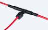
A flexible, clip-around, Rogowski probe for measuring hf common mode currents in VSD.
A flexible, clip-around, current probe to measure high frequency common mode currents which flow around a motor drive to ground via the bearings in large AC drive systems.
The CMC can also be used for in a variety of other applications where small, high frequency currents need to be measured.
The CMC is an important tool to identify the presence and severity of common mode currents in large motor drives. It is designed for use by experienced personnel with knowledge of AC drive systems. Once identified, the CMC will give an engineer a reference measurement which can be used to evaluate the effectiveness of steps taken to mitigate against bearing currents.
The probe is a modified version of our industry leading CWT range of Rogowski current sensors.
Key Features
- Wide operating temperature -20°C to +90°C.
- Low frequency (-3dB) bandwidth to attenuate large fundamental power frequency currents and magnetic fields.
- High frequency (-3dB) bandwidth of ≥10MHz.
- A wide range of Rogowski coil sizes.
- An electrostatically screened Rogowski coil.
- Coil insulation 10kV pk.
Applications
- Variable Speed Drives (VSD) that control AC motors produce fast transient PWM voltages that can capacitively couple to the machine shaft. The voltages on the shaft can be sufficient to cause arcing currents to flow through the motor bearings to ground. These currents can be measured by the CMC on the machine shaft or motor earthing mechanisms.
- Measuring interference in traction applications to ensure that the locomotive VSD doesn’t compromise the integrity of rail signalling systems.
Standards and Compliance
- CE marked
- Complies with EMC EN61326-1
- Complies with IEC 61010-1; IEC 61010-2-032
- PEM Ltd is certified to the ISO9001:2015 standard
- Patented product
PEM are committed to delivering the highest level of quality to our customers, read more about how we strive to achieve this in our Quality Standards and Compliance sections.
Key Features
-
Electrostatically shielded coil
Excellent immunity to interference from fast local dV/dt transients or large 50/60Hz voltages.
Patented Technology. -
Wide operating temperature
Wide operating temperature -20°C to +90°C.
-
Wide-bandwidth
High frequency (-3dB) bandwidth of ≥10MHz.
-
Insulated coil
Coil insulation 10kV pk.
-
Customise cable length
Longer cables than the standard 1m, 2.5m and 4m are available on request.
-
Custom coil length
Coil lengths longer than the standard 300mm, 500mm, 700mm and 1000mm are available on request.
-
Bespoke options
Choose from a range of standard options or create a custom design.
Performance
CMC Models
| Model | Sensitivity (mV/A) | Peak Current (A) | Noise(mVp-p) | LF (-3dB) (kHz) | Typical LF (<1%) (kHz) | Peak di/dt (kA/μs) | HF (-3dB) Bandwidth
(MHz)
|
|---|---|---|---|---|---|---|---|
| CMC/015 | 200 | 37.5 | 4.0 | 19 | 50 | 4.0 | 10 (1000) |
| CMC/03 | 100 | 75 | 4.0 | 6.0 | 15 | 8.0 | 10 (1000) |
| CMC/06 | 50 | 150 | 4.0 | 1.9 | 5.0 | 16 | 12 (1000) |
Noise - ‘Noise’ is the internally generated integrator noise, this is predominantly the same frequency as the LF (-3dB) bandwidth.
HF (-3dB) Bandwidth - The HF(-3dB) is specified for a 2.5m cable, we can supply longer coils sand cables on request.
di/dt ratings
These are ‘Absolute maximum di/dt ratings’ and values must not be exceeded.
| Type | Abs. Max. peak di/dt | Abs. Max. rms di/dt |
|---|---|---|
| CMC | 70kA/μs | 1.5kA/μs |
Technical Specifications
CMC
- Output
-
±7.5V pk corresponding to ‘Peak Current’ into ≥ 100kΩ (recommended e.g. DC1MΩ oscilloscope).
- Accuracy
-
Calibrated to ±0.5% reading with conductor central in the coil loop.
Variation with conductor position in the coil typically ±3% of reading (for a 5cm2 conductor) Linearity (with current magnitude) 0.05% of reading. - DC offset
-
±3mV max. at 25°C
- Temperature
-
Coil and cable -20°C to +90°C
Integrator electronics 0°C to +40°C - Coil voltage
-
10kV pk
Safe peak working voltage to earth.
Rating established by a 15kV rms, 50Hz, 60 sec flash test. - Cable length
-
2.5m or 4m (length of cable from coil to electronics).
(Longer cables are available on request). - Coil length
-
500mm, 700m or 1000mm.
(Longer coils are available on request). - Battery Options
-
BAlkaline Batteries -- 4 x 1.5V AA alkaline batteries.
External power adaptor disconnects batteries and powers unit.RRechargeable Batteries -- 4 x 1.2V NiMH batteries.
External power adaptor trickle charges batteries and powers unit.External power adaptor available in US, EURO, UK & AUS versions as an optional extra.
Dimensions
CWT / CWTHF/ CWTLF / CMC Dimensions
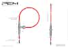
Coil Length and Sizing Guide
As a general 'guide to sizing' the coil, it will fit a circular conductor with a maximum diameter
= [Coil length / 3.3]
Standard Coil Lengths
300mm
500mm
700mm
1000mm
Longer coils can be made to meet specific requirements.
Minimum Bend Radius
What is included?
The CMC is supplied with some standard items so your measurement is ready to go the moment you receive your probe.
Details of how to specify a CMC probe including peak current rating, coil circumference, cable length and the type of batteries to power the electronic integrator can be found in the performance section.
If you want to purchase a CMC you can get a quote, if your requirement is outside that listed on our website please contact us to discuss your requirements and application.
-
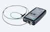
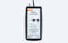
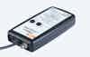
CWT Probe
Clip-around Rogowski coil, with cable connected to an electronic integrator housed in a plastic enclosure. The enclosure has an output BNC socket, ON/OFF switch, slide panel for batteries and socket for external DC power.
-
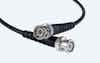
0.5m BNC Output Cable
Every CWT unit is supplied with a detachable 50ohm BNC to BNC output cable. (The CWTMini50HF output cable is fixed).
-

Carry Case
Robust hard plastic carry case with handle to protect the CWT probe in transit. Dimensions: 330mm x 265mm x 58mm.
-

Batteries
Choose from either (4 x 1.5V Alkaline) or (4 x 1.2V NiMH) Rechargeable AA Batteries. (The CWT has trickle charge capability for the NiMH battery option).
-

Calibration Certificate
Every unit is supplied with a fully traceable calibration certificate.

Customise & Options
PEM can customise CMC current probes, and supply optional items, that may be required for your specific measurement.
Customisation can be as simple as choosing coil lengths or cable lengths outside those specified on the datasheet, or you may have more complex requirements, see custom designs for some examples.
Additional optional items for the CWT range include a low noise wall mount power adaptor.
-

Longer Cables
Longer cables are available up to 100m.
(Custom lengths available on request) -
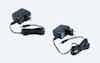
Power Adaptor
External power adaptor available in US, EURO, UK & AUS versions as an optional extra.
-
Longer Coils
Longer coils are available up to 16m.
(Custom lengths available on request)
Get a Quote
Build your CWT product options and complete our online quotation form.
Custom Design
We can provide custom designs for one off applications or volume manufacture.
Downloads
For more information and documents please see our full technical resources area.
-
Datasheets
XX21S and XX13S - Power Adaptor Technical Specification Datasheet PDF 505KB Updated: 6th January, 2026
-
Datasheets
CMC Datasheet PDF 471KB Updated: 13th November, 2025
-
Instruction Sheets
CMC Instruction Manual PDF 719KB Updated: 24th November, 2024
-
Dimension Drawings
CWT / CWTHF/ CWTLF / CMC Dimensions PDF 418KB Updated: 26th May, 2024
-
CAD Files
CWT / CMC Enclosure STEP 30.2MB Updated: 5th June, 2024
-
CAD Files
CWT / CMC / CWTLF COIL 10kV STEP 7.3MB Updated: 5th June, 2024
-
Technical Notes
High Frequency Bearing Currents Credentials PDF 270KB Updated: 26th November, 2025
-
Technical Notes
Voltage Immunity PDF 1.4MB Updated: 22nd October, 2024
-
Compliance
CWT / LFR / CMC / DCFlex Warranty PDF 197KB Updated: 9th January, 2025
Technical Resources
Browse our extensive resources of technical information, insights and test data.
Get a Quote
Build your CWT product options and complete our online quotation form.
Applications
For more information on possible and suitable applications please review the applications below and click each one for further information.
-
 High Frequency Bearing Currents
High Frequency Bearing Currents
High-frequency bearing currents represent a significant threat to modern motor systems driven by VFDs. PEM’s CMC Rogowski probe addresses this precise challenge with purpose-designed measurement capability for high-frequency bearing currents.About High-Frequency Bearing Currents
High-frequency bearing currents represent a significant threat to modern motor systems driven by variable frequency drives (VFDs). These transient electrical currents, generated by rapid semiconductor switching in power electronic converters, cause premature bearing failure through electrical discharge machining (EDM) effects. Unlike conventional mechanical wear, EDM damage progresses rapidly, potentially reducing bearing life from years to mere months.
These currents are characterised by extremely fast rise times (typically nanoseconds), high peak amplitudes (0.5-40A) and frequency components ranging from kilohertz to megahertz. When the voltage across a bearing exceeds the breakdown threshold of the lubricant film (typically 5-30V), electrical discharge occurs, creating microscopic craters on bearing surfaces that eventually develop into characteristic fluting patterns.
The technical challenge lies in accurately capturing these fast, transient phenomena in operational environments. Conventional current measurement tools lack the necessary bandwidth, risking millions in equipment damage and unplanned downtime across marine propulsion systems, water treatment facilities and critical industrial applications.
PEM’s CMC Rogowski Technology
PEM’s CMC Rogowski probe addresses this precise challenge with purpose-designed measurement capability for high-frequency bearing currents. Drawing on decades of expertise in power electronic measurement, our technology provides:
- Optimised high-frequency response
2kHz into the MHz range bandwidth specifically engineered to capture fast transients associated with VFD switching edges - Superior transient performance
Accurately measures current pulses with rise times as fast as 20ns - Non-invasive measurement
Flexible, clip-around design requires no electrical connection or circuit breaking - Air-core design
Eliminates magnetic saturation and hysteresis effects that compromise measurement accuracy - Electrostatic screening
Reduces capacitive coupling interference in electrically noisy environments
Key Features
- Frequency range: 2kHz to >10 MHz
- Fast transient response: Captures rise times as fast as 20ns
- Peak current measurement: Up to 150A peak
- Flexible sizing: Available in various diameters to accommodate different cable and shaft dimensions
- Rugged construction: Designed for harsh industrial environments
Applications
- Bearing protection verification
Confirm effectiveness of insulated bearings, shaft grounding rings and other mitigation measures - Condition monitoring
Detect developing issues before catastrophic failure occurs - Root cause analysis
Distinguish between different bearing current types (EDM, circulating, rotor ground) through waveform analysis - Design validation
Verify motor system designs against bearing current risk factors
Why PEM?
Measurement Expertise
Our technology is specifically designed for the unique challenges of high-frequency current measurement, with proven results in the most demanding industrial applications worldwide.
Application Knowledge
With extensive experience in bearing current phenomena across a range of industries, we understand the critical technical parameters that matter for your application.
Field-Proven Solutions
Our measurement systems have been deployed successfully in marine propulsion systems, water treatment facilities and industrial applications globally.
Talk to Us
Every electrical machine application presents unique measurement challenges. Whether you’re designing new systems, troubleshooting bearing failures, or implementing preventive maintenance programmes, PEM can help you build the right current sensing solution.
- Optimised high-frequency response
-
 Small AC on Large DC Currents
Small AC on Large DC Currents
Examples including measuring small ripple currents on a large magnitude DC bus.Rogowski current probes do not measure the DC component of a current. However unlike a current transformer or a fluxgate device they contain no magnetic materials so are unaffected by the DC current. Therefore it is possible to use a small, flexible, Rogowski coil to measure a small AC current in the presence of a large DC current, whereas a sensor based on a magnetic principle would be expensive and bulky to prevent saturation effects. One such common application is measuring the ripple current in capacitors where the main current is DC or slow time varying.


Quality Standards
We are committed to delivering the highest standards of excellence to customers.
Compliance
We prioritise compliance with industry standards ensuring all products are safe.